 HWAMDA
The five main systems at a glance
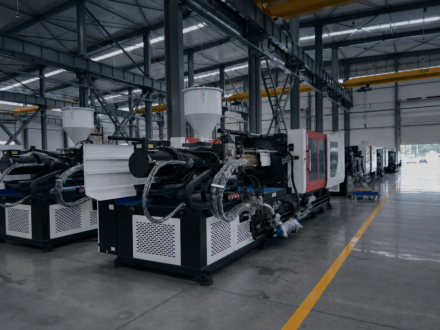
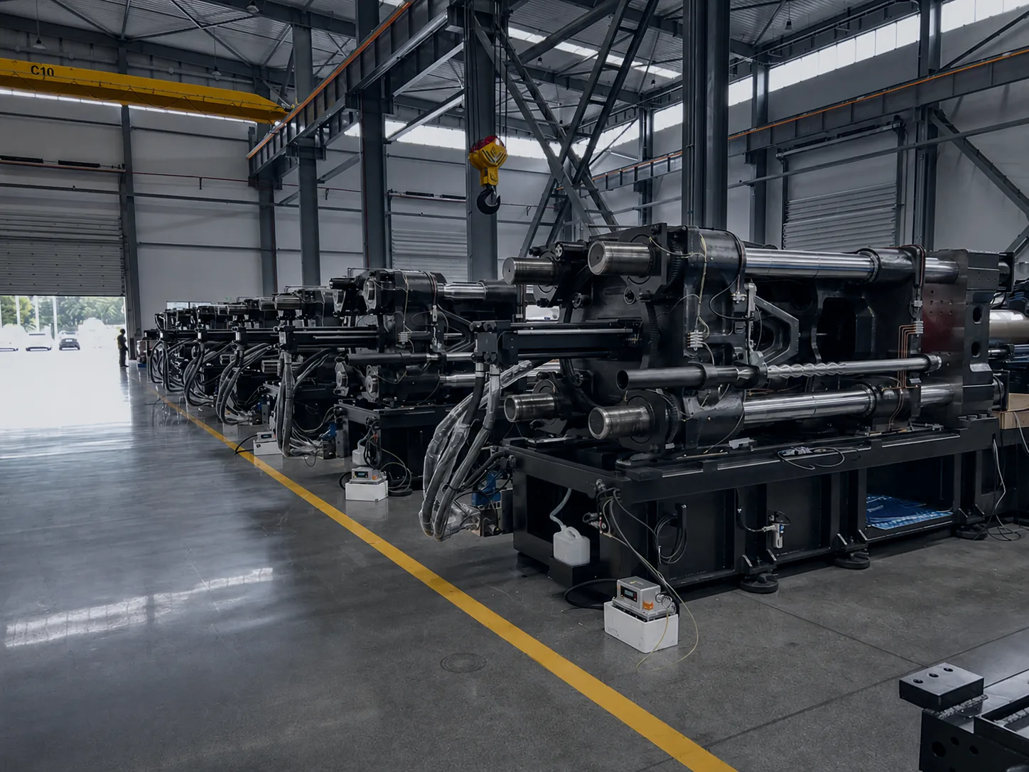
Every injection molding machine, from a small packaging machine to a large two-platen machine, is built from the same five systems. Knowing what each one does helps you compare machines, specify the right configuration and plan maintenance.
This guide covers the machine itself. The mold (cavities, cores, runner or hot runner, cooling and ejector pins) is a separate tool that is made for each product and mounted between the platens.
- Injection unit
- Melts the plastic and injects a measured shot into the mold.
- Clamping unit
- Opens and closes the mold and holds it shut against injection pressure.
- Hydraulic and drive system
- Supplies the force and movement for every axis of the machine.
- Electrical and control system
- Sets, sequences and monitors the whole molding cycle.
- Lubrication, air and safety
- Keeps moving parts lubricated, supplies compressed air and protects the operator.
Injection unit
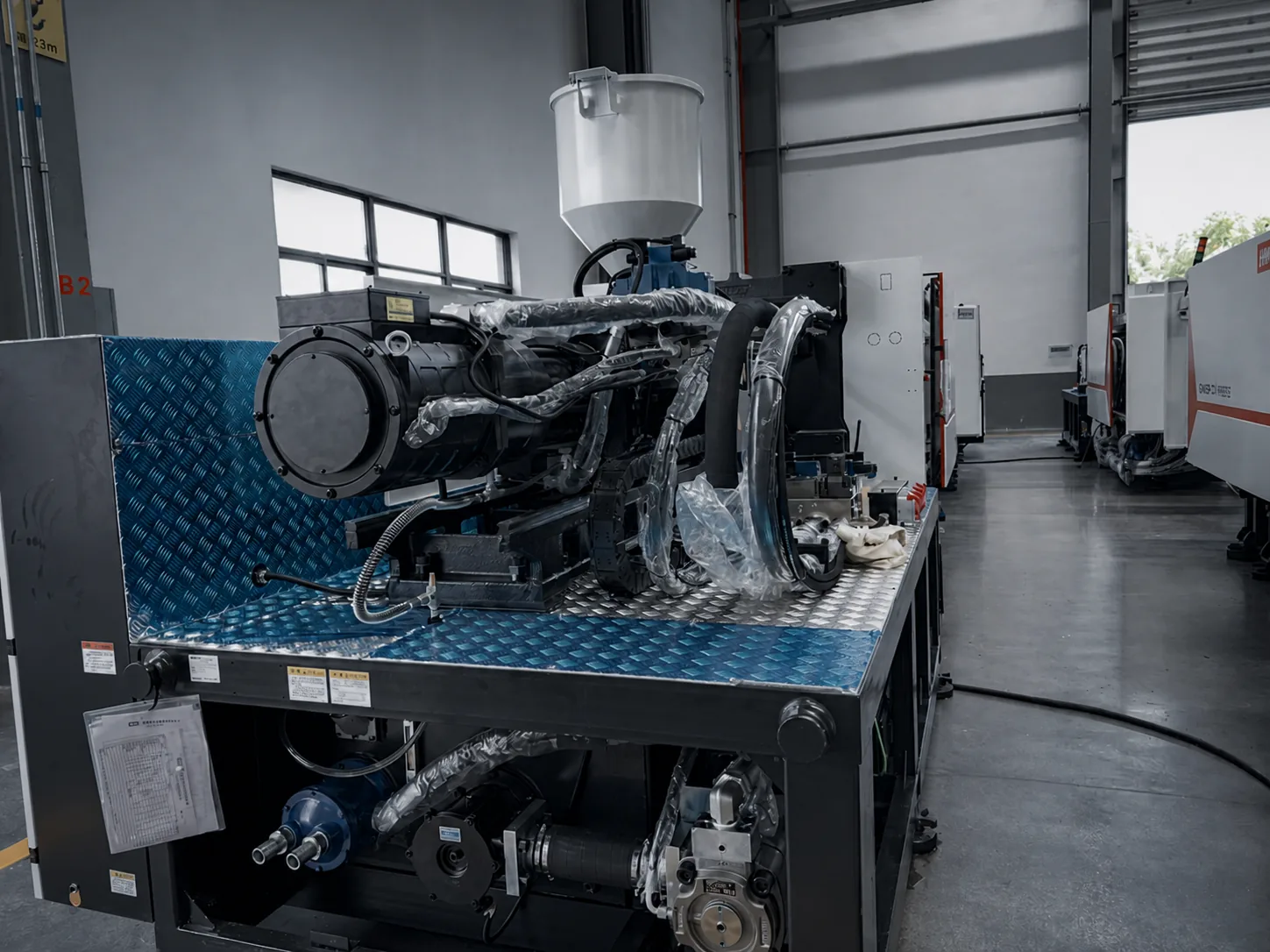
The injection unit turns plastic pellets into a uniform melt and pushes it into the mold. It sits on a carriage so that the nozzle can move forward against the mold and back away from it.
- Hopper
- Holds the pellets and feeds them into the barrel. A dryer or loader often sits on top of it.
- Barrel and heater bands
- The barrel surrounds the screw. Heater bands, controlled by thermocouples in several zones, bring it to processing temperature.
- Screw
- Rotates to convey, compress and melt the pellets, then moves forward like a ram to inject. Most of the heat for melting comes from the screw's shearing action. Screw design is matched to the material.
- Check ring (non-return valve)
- Lets melt flow in front of the screw during recovery and closes during injection, so the shot size stays consistent.
- Nozzle
- Connects the barrel to the mold's sprue bushing and seals against it during injection.
- Injection and carriage cylinders
- Drive the screw forward for injection and holding pressure, and move the whole unit toward or away from the mold.
Clamping unit
The clamping unit carries the mold. It closes the mold quickly, slows down for mold protection, builds clamping force so the mold stays shut while it fills, then opens and ejects the part. Clamping force is the figure most often used to describe machine size.
- Fixed and moving platens
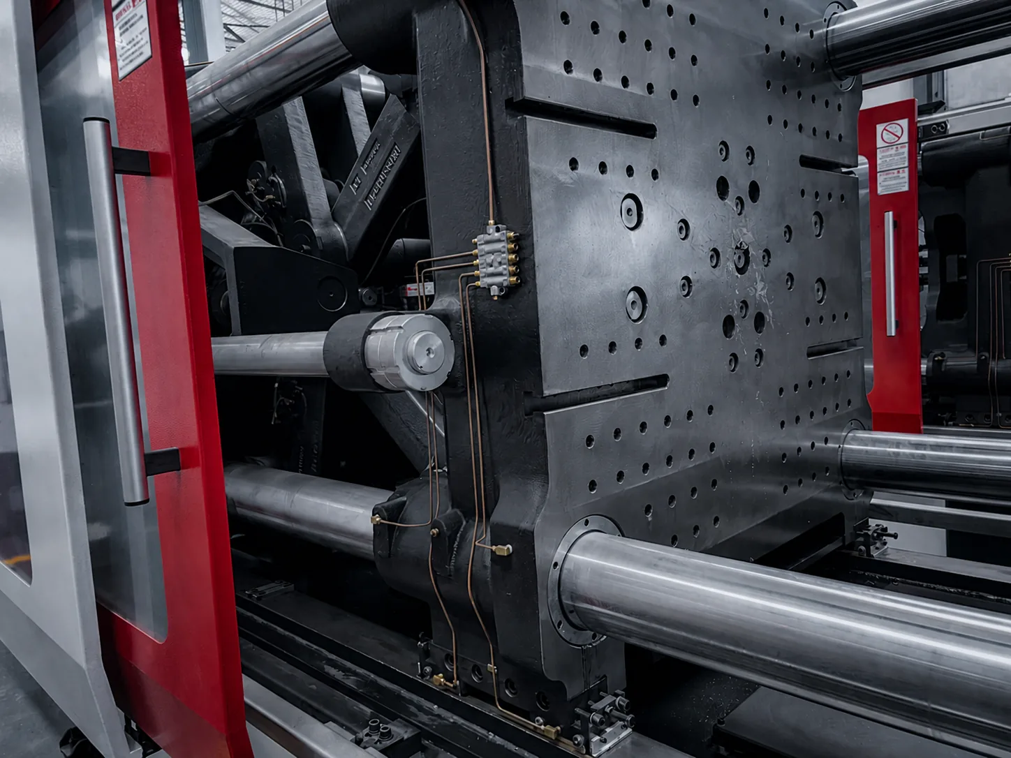
- The two mold halves are bolted to these heavy plates. Platen size and tie-bar spacing decide how large a mold fits.
- Tie bars
- Usually four steel bars that guide the moving platen and carry the clamping force.
- Toggle mechanism or clamp cylinders
- A toggle uses linked arms driven by a hydraulic cylinder to multiply force. A two-platen machine instead builds force with hydraulic cylinders acting directly on the tie bars, which saves length on large machines.
- Mold height adjustment
- Sets the distance between the platens to suit thicker or thinner molds.
- Ejector system
- Pushes the molded part off the core after the mold opens, through ejector pins or plates in the mold.
- Safety gates
- Guard the mold area. The machine cannot close while a gate is open.
Hydraulic and drive system
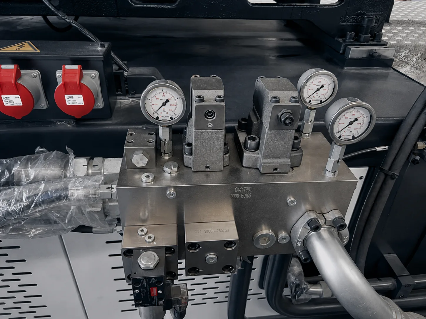
On hydraulic and servo-hydraulic machines, a motor drives a pump that supplies oil to cylinders and a hydraulic motor. In a servo-hydraulic machine, a servo motor changes pump speed to match demand, so the pump runs slowly or stops between movements. That is the main source of its energy savings over a fixed-speed pump.
- Motor and pump
- Generate oil flow and pressure. With a servo motor, flow follows each movement of the cycle.
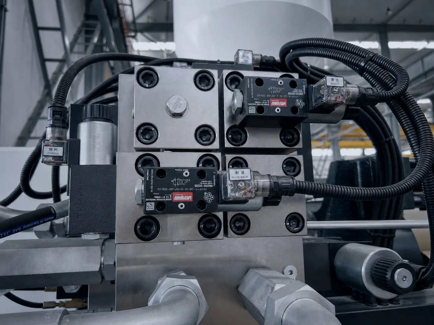
- Valve blocks
- Direct oil to the right cylinder at the right time and control pressure and speed.
- Cylinders and hydraulic motor
- Turn oil pressure into movement: clamp, injection, ejection, carriage and screw rotation.
- Oil tank, cooler and filters
- Store the oil, keep it at a stable temperature and keep it clean. Clean, cool oil protects valves and seals.
Electrical and control system
The controller is the operator's view of the machine. It stores the process settings for each mold, runs the cycle in sequence, watches temperatures, pressures, positions and times, and raises an alarm when a value leaves its limits.
- Controller and operator screen
- Set temperatures, speeds, pressures, positions and times; save mold recipes; view alarms and production counts.
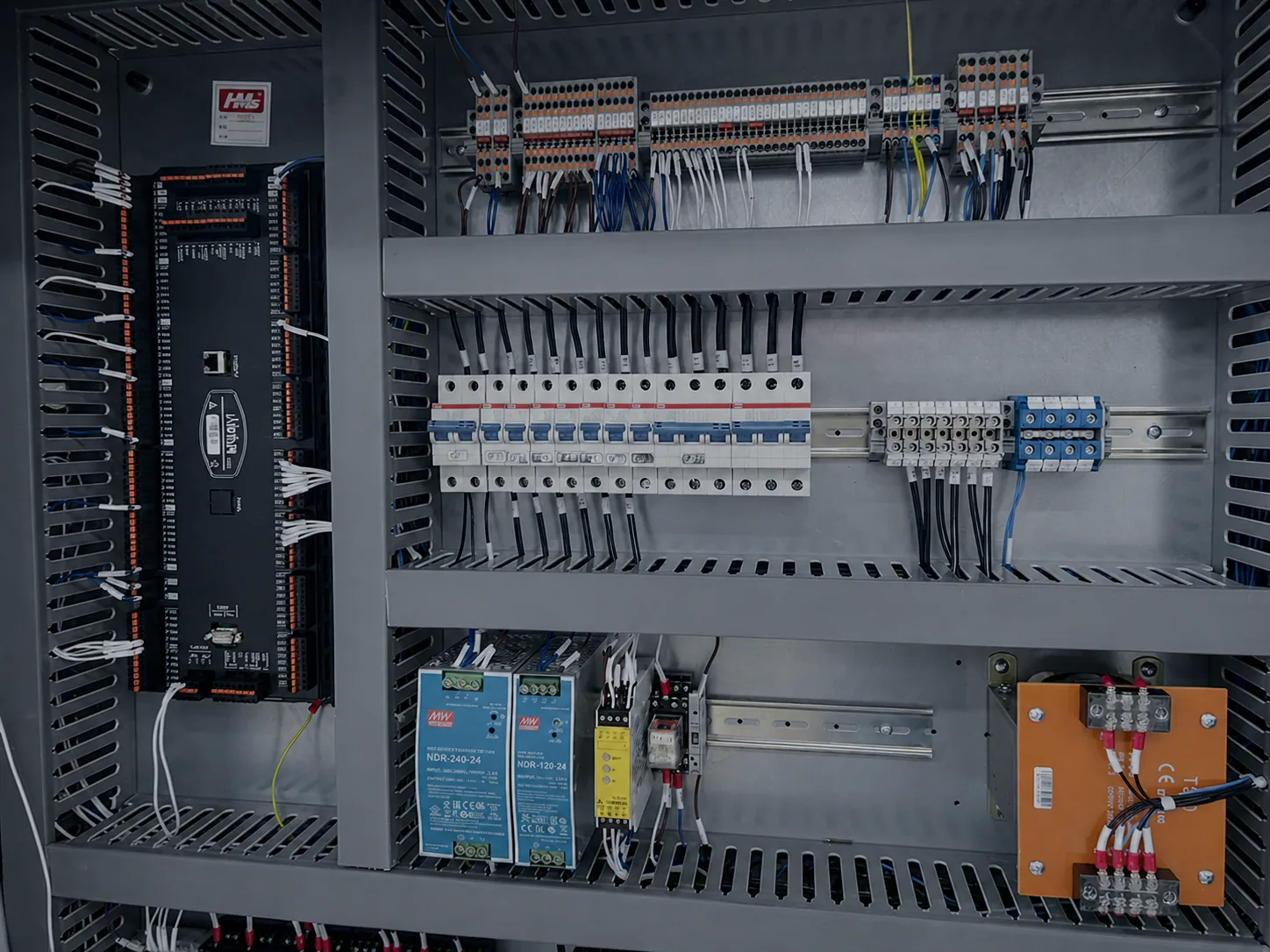
- Electrical cabinet
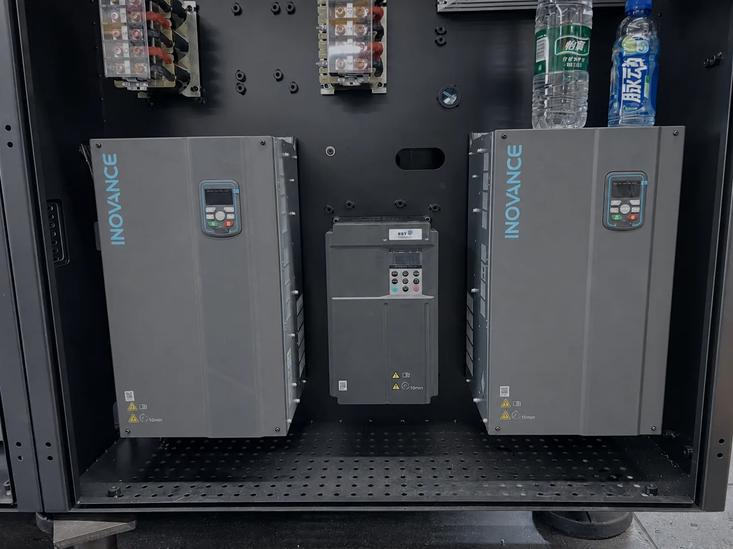
- Holds the power supply, circuit protection, relays, I/O modules and the drives for motors.
- Sensors
- Thermocouples, position transducers and pressure sensors feed real values back to the controller.
- Interfaces
- Signal connections for robots, mold temperature controllers, hot runner controllers and other auxiliaries.
Lubrication, air and safety
Smaller systems keep the machine running smoothly and safely. They are easy to overlook when comparing machines, but they decide how much daily attention a machine needs.
- Automatic lubrication
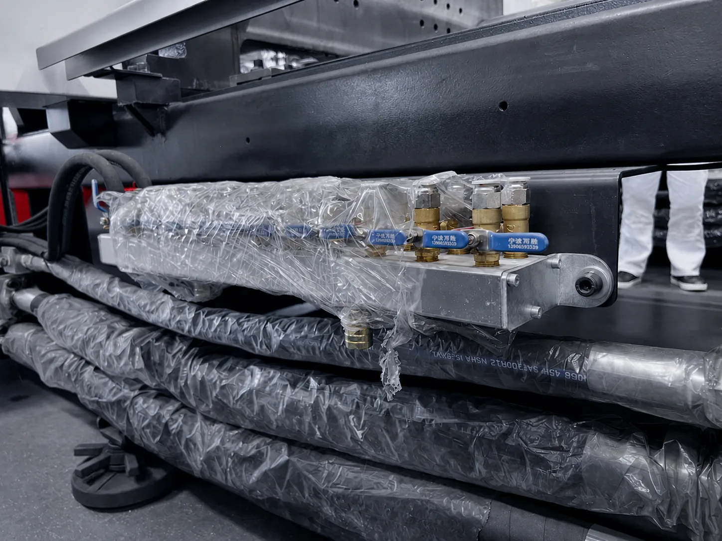
- A pump sends grease or oil through a manifold to the toggle pins, bushings and guides at set intervals.
- Compressed air supply
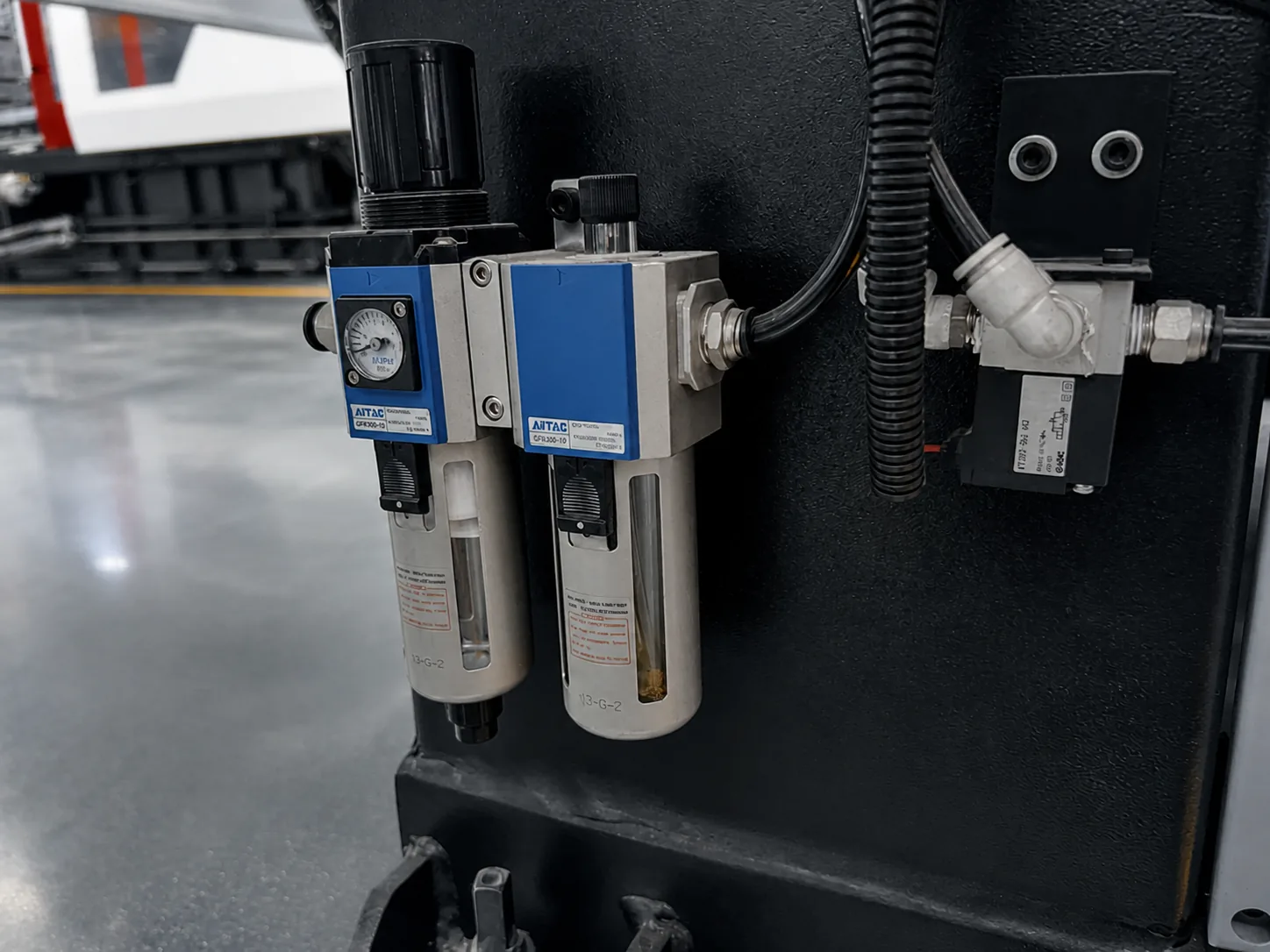
- A filter and regulator clean and set the air used for air blow, valve gates and some mold functions.
- Guards and interlocks
- Front, rear and top guards with electrical and hydraulic interlocks stop motion when the mold area is open.
- Emergency stop
- Stops all motion immediately from the operator side and other positions around the machine.
Component reference table
Use this table as a quick reference when you compare quotations or plan maintenance.
| Component | Main function | Typical wear or check point | What to confirm when buying |
|---|---|---|---|
| Screw and barrel | Melt and meter the material | Wear on flights and bore, faster with filled or abrasive materials | Screw diameter and design for your material and shot weight |
| Check ring | Stop melt flowing back during injection | Wear causes an unstable cushion and shot weight | Type suited to the material |
| Heater bands and thermocouples | Heat the barrel and measure temperature | Failed bands, loose connections | Number of heating zones |
| Nozzle | Seal the barrel to the mold | Leaks, blocked tip | Nozzle type and radius matched to the mold |
| Platens and tie bars | Carry the mold and the clamping force | Platen parallelism, tie-bar condition | Platen size, tie-bar spacing and mold height range for your mold |
| Toggle or clamp cylinders | Close the mold and build force | Pin and bushing wear if lubrication fails | Clamping force and opening stroke |
| Ejector system | Push the part off the core | Seal and guide wear | Ejector stroke and force |
| Motor and pump | Supply hydraulic power | Noise, oil temperature | Drive type: fixed pump or servo |
| Valves, cylinders and seals | Control and deliver movement | Leaks, contamination | Response for your cycle time |
| Hydraulic oil and filters | Transmit power, protect components | Contamination, overheating | Oil cooling and filtration |
| Controller and sensors | Run and monitor the cycle | Sensor drift, alarms | Interfaces for robots and auxiliaries |
| Lubrication system | Protect moving clamp parts | Blocked lines, empty reservoir | Automatic lubrication |
Choosing a machine by its components
Two machines with the same clamping force can be very different machines. Start from your product and mold, then check the components that matter for them: the screw and shot size for your material and part weight, platen size and tie-bar spacing for your mold, opening stroke for deep parts, the drive type for your energy costs and cycle, and the controller interfaces for the robot and auxiliaries you plan to use.
Send us your part drawing, material and mold information. HWAMDA will propose the machine model and injection unit that fit, and explain the configuration line by line.
Replacement parts and warranty
Wear parts such as check rings, heater bands, thermocouples, seals and filters are worth keeping in stock so that a small failure does not stop production. HWAMDA machines carry a 1-year machine warranty, 2 years on tie bars and 5 years on platens.
FAQ
Frequently asked questions
What are the main parts of an injection molding machine?
The injection unit, the clamping unit, the hydraulic and drive system, the electrical and control system, and the lubrication, air and safety systems. The mold is a separate tool mounted in the clamping unit.
What is the difference between machine components and mold components?
Machine components belong to the injection molding machine and are used for every product it runs. Mold components, such as cavities, cores, runners and ejector pins, belong to the mold, which is made for one product.
Which components wear first?
Usually the check ring, screw and barrel, heater bands, thermocouples, seals and filters. Wear is faster with glass-filled or abrasive materials and with long running hours.
What does the screw do in an injection molding machine?
It conveys, compresses and melts the pellets as it rotates, then moves forward like a piston to inject the melt into the mold.
What is the difference between a toggle clamp and a two-platen clamp?
A toggle clamp multiplies the force of one cylinder through linked arms. A two-platen clamp uses hydraulic cylinders acting on the tie bars, which makes large machines shorter.