 HWAMDA
Place the printed film
A pre-cut label enters the open cavity before the resin. Its printed face and edges must follow the intended decoration area.
IML PROCESS GUIDE
Understand how the label, robot, mold and injection molding machine work as one synchronized process before configuring an IML production cell.
01
In-mold labeling places a prepared label inside the mold before injection. The molten plastic forms against it so the label becomes part of the molded product.
Label is placed before injection
Plastic forms against the label
Robot and mold define placement
Finished part exits with decoration
02
IML combines label presentation, robot movement, mold access, injection, cooling and part removal in a controlled sequence.
A pre-cut label enters the open cavity before the resin. Its printed face and edges must follow the intended decoration area.
The handling system retains the film against the cavity surface until filling begins. The retention method depends on the tooling and label.
Heat, pressure and compatible materials allow the label and molded plastic to bond. This is why film selection is part of process development.
The part cools before ejection. Inspect label position, surface appearance and bonding as well as the dimensions of the molded part.
03
The cycle is only stable when every connected step is ready at the correct time.
04
Label material, geometry, orientation, separation and static behavior must match the real product and handling method.
PP film is common with PP containers. Confirm the actual film construction and resin combination with the label supplier; appearance alone does not establish compatibility.
The die-cut outline must follow the decorated surface. Corners, wrap-around edges and coverage changes affect how the film lies in the cavity.
Curled edges or labels that cling together can disturb pickup. Examine the stored label stack and how individual sheets separate.
Some systems use electrostatic charge to retain labels in the cavity. Static at the magazine can also hinder separation, so these two locations need different handling checks.
05
The mold must provide repeatable label placement, robot clearance, balanced filling, cooling and part release.
The label must rest against the intended cavity surface without folds. Its shape and placement influence the visible decorated area.
The advancing melt meets the label during filling. Gate location and the fill profile therefore matter when investigating label displacement.
Air must leave as plastic fills the cavity. If surface defects recur in the same area, include local venting and label contact in the investigation.
Cooling and ejection must preserve the part shape and decorated surface. Inspect distortion after cooling, not only the appearance at mold opening.
Discuss cavity, gate and vent changes with the mold designer. HWAMDA can support machine–mold matching and coordinated production trials.
06
The robot positions labels and removes parts while exchanging safety and ready signals with the machine.
The end-of-arm tool must collect one label in a repeatable orientation. A double pickup can look like a placement fault later in the cycle.
The label needs support during travel. Movement that bends or shifts the film changes where its edges arrive in the cavity.
The tool positions the film, transfers it to the cavity and withdraws. Observe each handover when separating pickup errors from retention errors.
The robot removes the cooled part and clears the mold area. Machine and robot permissions coordinate the next closure; movements may overlap only within the designed sequence.
07
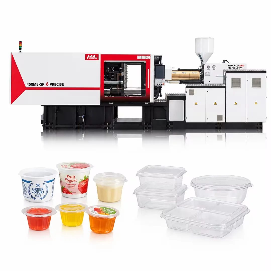
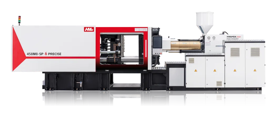
The machine must provide stable response, repeatable control, suitable mold movement and automation interfaces for the complete cycle.
Changes in the flow front can alter the forces acting on the label. Evaluate repeatability using both molded-part quality and label position.
Opening travel must allow the tooling to enter and leave. More travel is not automatically better: unnecessary movement adds time to the sequence.
Plasticizing must prepare the next shot while maintaining the material condition. Otherwise recovery can become the step that limits output.
Ready, position and fault signals connect molding to handling. A robot waiting for a signal is a different cycle-time issue from slow cavity cooling.
08
IML integrates decoration during molding, but benefits depend on the validated product, label, mold and production system.
Decoration is applied during molding rather than in a separate post-molding step.
The robot and mold can repeat a validated label position.
The final structure can protect the printed surface according to label construction.
Label placement and part take-out can be combined in one synchronized sequence.
09
Containers, cups, boxes, lids, buckets and other compatible packaging parts can be reviewed for IML.
A decorated sidewall must still meet the required lid fit, stacking behavior and dimensional stability.
Taper and curved walls influence the label outline and the way a film wraps around the cavity.
Corners and flat panels introduce different placement conditions within one decorated surface.
Check that decoration does not interfere with the sealing or engagement features of the lid.
Larger decorated areas require attention to film support, coverage and consistent positioning.
10
Food-container projects often combine thin-wall filling, label placement, fast cooling, take-out and stacking requirements.
Review the Food Container SolutionThin-wall filling window
Accurate label position
Balanced mold cooling
Reliable part take-out and stacking
11
Problems should be diagnosed across label, robot, mold, machine, static control and timing.
Possible causes include pickup orientation, movement during transfer or loss of retention. Compare its position before injection with the finished part to locate when the shift starts.
Possible causes include film that does not lie flat, outline mismatch or local air escape. Compare the defect location with label edges, cavity geometry and venting.
Inspect sheet separation, pickup and the label-detection stage first. A feed fault occurs before the molding parameters can affect the decoration.
Identify where the sequence waits: label preparation, robot clearance, cooling or ejection. Inspect part support and release before treating every delay as a machine-speed problem.
12
The two methods differ mainly in when decoration is added and which equipment becomes part of production.
| Decision factor | In-mold labeling | Conventional labeling |
|---|---|---|
| Decoration timing | Inside the molding cycle | After the part is molded |
| Core equipment | Label feeder, robot, mold and machine | Molding plus separate labeling equipment |
| Change control | Label, mold and robot sequence are linked | Labeling is managed downstream |
| Project validation | Complete cell must be trialed together | Molding and labeling can be validated separately |
13
A complete cell coordinates the machine, mold, robot, label handling and automation controls.
14
Practical answers for planning an IML process.
It is a decoration process in which a printed label is placed inside the mold and becomes bonded to the plastic during molding. The part leaves the mold already decorated.
A robot places the label in the open cavity, the label is retained, and the mold closes. Plastic is injected against the label, then the decorated part cools and is removed.
The process uses an injection machine, compatible mold, label supply, placement tooling, robot and coordinated controls. The retention and downstream handling methods depend on the product.
The machine must support the part’s molding requirements and the robot sequence. An IML label alone does not define the machine size or require one particular drive technology.
The mold must accommodate label placement, retention, filling and removal. A conventional mold may need changes; its suitability cannot be inferred from part dimensions alone.
Injection-molded containers, cups, boxes, lids and buckets are common examples. Label coverage, geometry, resin compatibility and end-use requirements determine suitability.
Yes, it can combine decoration with thin-wall molding. Film, resin, filling, cooling and handling must work together, and the finished packaging must meet its intended food-contact requirements.
Filling, cooling, plasticizing, mold travel, label preparation and robot movements all contribute. Some steps overlap; the limiting step determines whether a faster individual movement improves total output.
Examples include displaced labels, wrinkles, missing or doubled labels, poor bonding and take-out damage. Find the stage at which the fault first appears, then investigate the material, tooling or handling conditions at that stage.