 HWAMDA
Geometry
Ribs, corners, transitions and draw direction change the filling path.
THIN-WALL PROCESS GUIDE
Understand how part geometry, material, flow length, machine response, mold design and cooling work together before selecting production equipment.
01 · DEFINITION
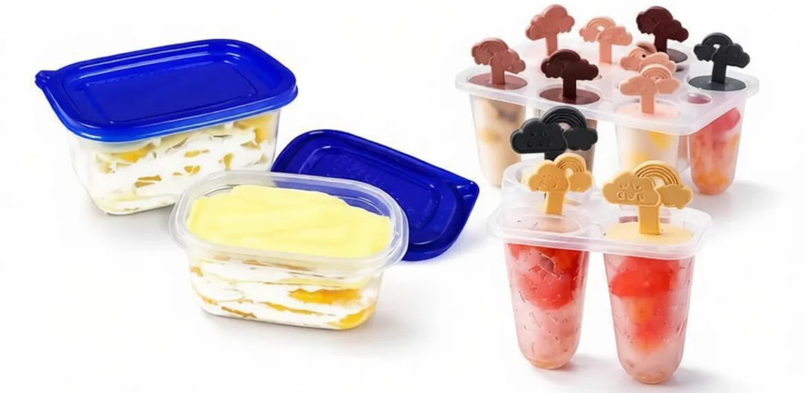
Thin-wall injection molding produces parts with long or demanding flow paths relative to their wall section. The process window is narrower because the melt must fill the cavity before the flow front freezes.
Part geometry and projected area
Nominal and local wall sections
Material flow behavior
Distance from gate to the end of fill
02 · WALL CRITERIA
There is no reliable universal thickness threshold for every plastic part. A wall that is routine for one geometry and resin may be difficult for another.
Ribs, corners, transitions and draw direction change the filling path.
Viscosity, stiffness, shrinkage and processing window affect feasibility.
A longer path raises the demand on filling speed, pressure and venting.
Overall projected area affects clamp and mold requirements.
Judge the complete part and flow path—not one isolated wall-thickness number.
03 · PROCESS WINDOW
The thinner flow channel loses heat faster and leaves less time to fill, pack and stabilize the part.
Wider filling window
Lower sensitivity to small timing changes
More forgiving flow path
Faster flow-front freezing
Higher sensitivity to speed and balance
Stronger dependence on cooling and venting
04 · MATERIALS
Material choice must balance flow, stiffness, impact, temperature, compliance and the finished product—not just ease of filling.
Common in thin-wall packaging; grade selection depends on stiffness, flow and end-use requirements.
Used where toughness and chemical resistance are relevant; geometry and grade remain decisive.
Can provide rigidity and clarity in suitable applications, with impact and product requirements considered.
Possible for specific technical parts, but processing, mold and performance requirements vary widely.
For high stiffness, compare actual grades, additives, wall design and test data from the material supplier. A polymer name alone is not enough.
05 · FLOW-LENGTH RELATIONSHIP
As the distance from the gate increases or the wall decreases, the filling demand rises. Gate position and balanced flow paths can change the result.
Use the real part drawing, resin grade, gate concept and mold-flow evidence when available. Do not treat one generic ratio as a universal pass/fail rule.
06 · INJECTION SPEED & PRESSURE
Thin-wall filling often needs rapid, repeatable machine response, but speed and pressure must be matched to the part and mold.
Reach the required fill condition consistently.
Control the flow front through changes in geometry.
Maintain a suitable process margin without masking mold problems.
Switch from filling to holding at a repeatable cavity condition.
07 · MACHINE REQUIREMENTS
A suitable machine is selected around the part, mold and target output. “High speed” is useful only when the complete process needs and supports it.
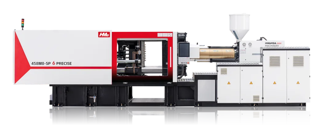
Stable acceleration and velocity control for the required fill profile.
Adequate force, platen fit and mold movement for the real projected area.
Prepare the next shot inside the intended cycle without degrading material.
Coordinate injection, cooling, ejector and automation signals.
Reserve safe, clear interfaces for take-out or IML equipment.
08 · MOLD DESIGN
Thin-wall performance cannot be corrected by the machine alone. The mold determines the flow path, heat removal, air escape and cavity-to-cavity consistency.
Gate type and location should support the intended flow path.
Trapped air must escape without creating flash.
Balanced circuits remove heat consistently across the part.
Multi-cavity filling and cooling should be reviewed together.
HWAMDA can review machine–mold interface data and coordinate production trials around the confirmed project requirements.
09 · COOLING & CYCLE
Cooling usually occupies a major part of the cycle. Uneven heat removal can create distortion even when filling appears acceptable.
The fastest possible motion is not the same as the fastest stable production cycle.
10 · DEFECT DIAGNOSIS
Treat each defect as evidence from a connected system: part, resin, drying, machine, mold, cooling and automation.
Possible causes include early freezing, restricted flow, insufficient venting or an unsuitable fill profile.
Often linked to uneven cooling, orientation, packing or wall distribution.
Review clamp condition, mold fit, venting, pressure and parting-line condition.
Check gate balance, cavity balance, temperature, venting and injection profile.
11 · APPLICATIONS
Suitability still depends on the real product drawing and performance requirements.
Light packaging parts with demanding filling, cooling and take-out.
Thin cylindrical parts where roundness and stacking may matter.
Light parts requiring balanced filling and reliable handling.
Other containers and closures reviewed by geometry, material and output.
12 · EQUIPMENT DECISION
Consider a high-speed configuration when the part and production window require faster response, shorter filling time and tightly coordinated mold and automation movements.
Explore High-Speed Thin-Wall Injection Molding MachinesThin or demanding flow path
High cavity count or output target
Narrow filling window
Fast mold and take-out sequence
Stable recovery inside the target cycle
13 · FAQ
Technical answers for early project evaluation.
It is a process for parts whose wall section and flow path create a narrow, fast-freezing filling window.
It depends on geometry, resin, flow length and part size; no single thickness defines every project.
The melt often must reach the end of the flow path before the thin channel freezes.
PP is common, while PE, PS and engineering plastics may fit specific applications. Select the actual grade from functional and processing data.
Balanced heat removal affects cycle, shrinkage, warpage and cavity consistency.
Possible causes include early freezing, flow restriction, poor venting, temperature or an unsuitable injection profile.
A machine with the required injection response, clamp and platen fit, recovery, control and automation interfaces for the real project.
A thinner part may cool quickly but becomes harder to fill; the stable cycle depends on the full part, mold, material and handling sequence.