 HWAMDA
The Basic Principle
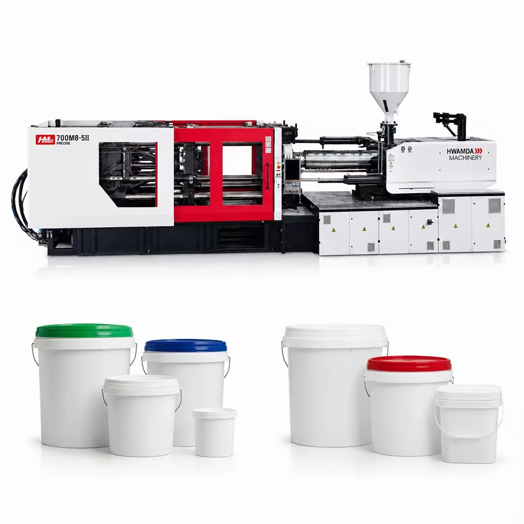
An injection molding machine melts plastic pellets, injects the melt under high pressure into a closed mold, holds it under pressure while it solidifies, then opens the mold and ejects the finished part. The cycle repeats automatically, often every few seconds for thin-wall packaging and every 30 to 90 seconds for thick technical parts.
Every machine, whether small or very large, is built from the same main units. Understanding what each unit does, and how the cycle time is divided between them, is the basis for choosing a machine, setting a process and finding the cause of defects.
Main Units of an Injection Molding Machine
- Injection unit
- Hopper, barrel with heater bands, reciprocating screw, check ring and nozzle. It melts the material and injects a measured shot into the mold at controlled speed and pressure.
- Clamping unit
- Fixed platen, moving platen, tie bars and a toggle or hydraulic clamp mechanism. It opens and closes the mold and holds it shut against injection pressure, and includes the ejector system that pushes parts off the core.
- Hydraulic or drive system
- Pump, motor, valves, cylinders and oil cooling on hydraulic and servo-hydraulic machines, or servo motors and ball screws on electric axes. It powers every movement of the machine.
- Control system
- The controller sets and monitors temperatures, speeds, pressures, positions and times, sequences the cycle, records process data and manages safety interlocks and interfaces to robots and auxiliaries.
- Mold
- Cavities and cores that shape the part, a runner or hot runner system to distribute the melt, cooling channels to remove heat, and an ejection system. The mold is specific to the part; the machine is the platform that runs it.
The Molding Cycle Step by Step
Each cycle follows the same sequence. Times vary with part design and material, but the proportions below are typical for a part with walls of 1.5 to 3 mm. Cooling is almost always the longest phase, usually 50 to 70 percent of the cycle, which is why mold cooling design and wall thickness have the largest effect on output.
Plasticizing for the next shot happens in parallel with cooling, so it does not add to cycle time as long as the screw finishes recovery before the mold opens.
| Step | What happens | Typical share of cycle |
|---|---|---|
| 1. Mold close and clamp | The moving platen closes the mold quickly, slows for mold protection, then builds clamping force | 5 to 10 percent |
| 2. Injection (fill) | The screw moves forward as a ram and fills the cavities at controlled speed, typically to about 95 to 98 percent full | 5 to 10 percent |
| 3. Pack and hold | Pressure switches from speed control to pressure control and packs extra melt to compensate for shrinkage until the gate freezes | 10 to 20 percent |
| 4. Cooling | The part solidifies in the mold while the screw rotates back and plasticizes the next shot | 50 to 70 percent |
| 5. Mold open | The clamp releases pressure and opens the mold to the set stroke | 5 to 10 percent |
| 6. Ejection and removal | Ejector pins, plates or air push the part off the core, or a robot removes it | 5 to 10 percent |
For thin-wall packaging the whole cycle can be under 5 seconds, with filling in 0.1 to 0.3 seconds.
Plasticizing: How the Screw Melts the Material
A reciprocating screw has three zones. In the feed zone, deep flights convey pellets from the hopper and start to warm them. In the compression or transition zone, the flight depth decreases, compressing the material against the heated barrel wall and melting it mainly by shear. In the metering zone, shallow flights homogenize the melt and deliver it to the front of the screw at uniform temperature.
Most of the melting energy comes from shear generated by screw rotation, not from the heater bands. The heaters set and stabilize the barrel temperature profile, which typically rises from the feed zone to the nozzle.
As the melt collects in front of the screw, it pushes the screw backward. Back pressure is the hydraulic resistance applied to this movement. Moderate back pressure improves mixing, removes trapped air and gives a more consistent shot. Too much increases shear heat and recovery time, which can degrade sensitive materials. A check ring at the screw tip prevents melt from flowing back during injection, so the shot weight stays repeatable.
Typical Process Parameters
The values below are typical starting ranges for common materials. Every grade, part and mold needs its own optimized settings, so use them as a starting point and confirm with the material supplier's data sheet.
- Injection speed
- Set by wall thickness and flow length; thin walls need very fast fill to avoid premature freezing.
- Switchover point
- The position at which the machine switches from fill speed to holding pressure, usually when the cavity is about 95 to 98 percent full.
- Holding pressure and time
- Typically 30 to 70 percent of peak injection pressure, held until the gate freezes, which can be confirmed with a gate-freeze weight study.
- Cushion
- A small amount of melt left in front of the screw at the end of hold, often 3 to 10 mm, shows that the shot is complete and consistent.
| Material | Melt temperature (C) | Mold temperature (C) | Drying | Typical injection pressure (bar) |
|---|---|---|---|---|
| PP | 200 to 260 | 20 to 50 | Not usually required | 600 to 1,500 (higher for thin wall) |
| HDPE | 200 to 280 | 20 to 60 | Not usually required | 600 to 1,400 |
| PS / HIPS | 180 to 260 | 20 to 60 | Not usually required | 600 to 1,400 |
| ABS | 210 to 260 | 40 to 80 | 80 °C for 2 to 4 h | 700 to 1,500 |
| PC | 280 to 320 | 80 to 110 | 120 °C for 3 to 4 h | 1,000 to 1,800 |
| PA6 / PA66 | 240 to 290 | 60 to 90 | 80 °C for 4 h (dry to below 0.2 percent moisture) | 700 to 1,500 |
| PET (preforms) | 270 to 290 | 10 to 20 (chilled) | 160 to 180 °C for 4 to 6 h at dew point -40 °C or lower | 800 to 1,500 |
| Rigid PVC | 170 to 200 | 20 to 50 | Usually not required | 800 to 1,500 |
How a Servo-Hydraulic Drive Works
In a conventional hydraulic machine, an induction motor runs the pump at constant speed, and valves throttle the flow that the cycle does not need. The excess energy turns into heat in the oil. During cooling, when the machine is mostly waiting, the pump still runs.
A servo-hydraulic machine drives the pump with a servo motor controlled by the machine controller. Motor speed and torque follow the flow and pressure demand of each phase of the cycle: high speed during fast movements and injection, low speed with high torque during holding, and near standstill during cooling. This reduces energy use and oil temperature, lowers noise and gives precise, repeatable pressure and speed control.
HWAMDA's M8SII series and the machines based on it use servo-hydraulic drives, combining the force and robustness of hydraulics with efficient, responsive control across 900 to 33,000 kN.
Auxiliary Equipment in the Molding Cell
HWAMDA supplies these items with machine projects so the cell can be planned, matched and commissioned as one system.
- Resin dryer
- Removes moisture from hygroscopic materials such as PET, PA and PC before molding to prevent splay and loss of properties.
- Hopper and vacuum loaders
- Convey material from bags, octabins or central storage to the hopper automatically.
- Chiller
- Supplies cooled water to the mold and to the machine's oil cooler.
- Mold temperature controller
- Holds the mold at a stable temperature, heating or cooling as needed for consistent part quality.
- Robot
- Removes parts and runners, places them on conveyors or stackers, and handles labels or inserts in IML and insert molding.
- Granulator
- Regrinds runners and rejects for controlled reuse where the product allows.
Common Defects and Their Usual Causes
| Defect | Appearance | Common causes |
|---|---|---|
| Short shot | Part not completely filled | Insufficient shot size, speed or pressure; melt too cold; poor venting |
| Flash | Thin excess plastic at the parting line | Clamping force too low, excessive pressure, worn or damaged mold |
| Sink marks | Depressions over thick sections | Insufficient holding pressure or time, thick walls, high melt temperature |
| Warpage | Part distorts after ejection | Uneven cooling, unbalanced shrinkage, ejection too early |
| Splay or silver streaks | Streaks on the surface | Moisture in material, degraded melt, excessive shear |
| Burn marks | Dark marks at end of fill | Trapped air from poor venting, injection speed too high |
| Weld lines | Visible lines where flow fronts meet | Low melt or mold temperature, slow injection, gate position |
FAQ
Frequently asked questions
What are the main parts of an injection molding machine?
The injection unit, clamping unit, hydraulic or drive system, and control system, together with the mold that shapes the part.
Which part of the cycle takes the longest?
Cooling, typically 50 to 70 percent of the cycle. Wall thickness, material and the mold's cooling design have the largest effect on it.
How does the screw melt the plastic?
Mostly through shear as the screw rotates and compresses the material in the transition zone. Heater bands stabilize the barrel temperature and supply the remaining heat.
What is back pressure?
Back pressure is the resistance applied to the screw as it moves back during plasticizing. Moderate back pressure improves melt mixing and shot consistency; too much causes excess shear heat.
What is the switchover point?
It is the screw position at which the machine switches from speed-controlled filling to pressure-controlled holding, usually when the cavity is about 95 to 98 percent full.
Why must some materials be dried?
Hygroscopic materials such as PET, PA and PC absorb moisture, which causes splay and degrades the polymer during melting. PET is typically dried at 160 to 180 °C for 4 to 6 hours at a dew point of -40 °C or lower.
What is the advantage of a servo-hydraulic drive?
The pump runs only as fast as each phase of the cycle requires, reducing energy use and oil heating while giving precise and repeatable control of speed and pressure.
Does HWAMDA provide training on machine operation?
Yes. HWAMDA project support includes installation and commissioning, operator training, maintenance guidance and remote technical support.