 HWAMDA
A Step-by-Step Selection Method
Selecting an injection molding machine works best when you start from the part and the mold, not from a tonnage figure. Each step below narrows the range of suitable machines, and the final choice is the smallest machine that meets every requirement with a sensible margin.
Collect the data first: part drawing or 3D model, material grade, part weight, wall thickness, flow length, number of cavities, runner type, mold dimensions and weight, target cycle time and annual output. With these numbers, every step can be calculated rather than estimated.
- 1. Calculate clamping force
- Projected area of all cavities and runners multiplied by the typical cavity pressure for the material and wall thickness, plus a margin.
- 2. Check shot size
- Total shot weight should use roughly 20 to 80 percent of the screw's shot capacity.
- 3. Choose the injection unit
- Screw diameter, L/D ratio and injection pressure suited to the material and flow length.
- 4. Confirm mold fit
- Tie-bar spacing, platen size, mold thickness range, opening stroke and ejector.
- 5. Check speed and pressure
- Thin-wall and long-flow parts need high injection rate and pressure.
- 6. Check plasticizing rate
- The screw must melt the next shot within the available cooling time.
- 7. Choose drive type and options
- Servo-hydraulic, two-platen or specialized series; core pulls, valve gates, robot interface.
- 8. Plan automation and utilities
- Robot, IML, dryer, chiller, mold temperature control, power and water.
Clamping Force Calculation with a Worked Example
Clamping force must exceed the force the melt exerts on the mold as it fills and packs. The standard estimate is: clamping force = total projected area x average cavity pressure x safety factor. Projected area is the area of the part as seen in the direction of mold opening, for every cavity plus any cold runner on the parting line. Holes inside the part outline are subtracted only if they are fully shut off by steel.
Worked example: an ABS electronics housing with an outline of 150 x 100 mm, molded in two cavities with a cold runner. Projected area per cavity is 15 x 10 = 150 cm2, so two cavities give 300 cm2. The runner adds about 20 cm2, for a total of 320 cm2. With 2 mm walls and moderate flow length, a typical cavity pressure for ABS is about 300 kgf/cm2. Force = 320 x 300 = 96,000 kgf, or 96 tf, which is about 940 kN. Adding a 15 percent margin gives roughly 1,080 kN, so a machine of about 1,100 to 1,300 kN is the starting point, subject to the mold fit check.
A thin-wall example shows how quickly pressure changes the answer. A four-cavity PP lid with a 120 mm diameter has a projected area of about 113 cm2 per cavity, or 452 cm2 in total. At 0.6 mm wall, cavity pressure of about 500 kgf/cm2 is typical, giving 226 tf or about 2,220 kN before margin. The same lid at 1.5 mm wall would need far less. HWAMDA's tonnage calculator applies the same method.
| Material | Typical cavity pressure, standard wall (kgf/cm2) | Typical cavity pressure, thin wall or long flow (kgf/cm2) | Notes |
|---|---|---|---|
| PP | 250 to 350 | 400 to 600 | Most common thin-wall packaging resin |
| HDPE | 200 to 350 | 350 to 500 | Crates, caps, buckets |
| PS / HIPS | 150 to 300 | 300 to 450 | Easy flow, cups and disposables |
| ABS | 250 to 400 | 400 to 500 | Housings, appliance parts |
| PC | 350 to 500 | 500 to 700 | High viscosity, needs high pressure |
| PA (PA6, PA66) | 300 to 450 | 450 to 600 | Low viscosity but fast freezing |
| PET (preforms) | 350 to 500 | Not typical | Thick walls, long hold times |
| Rigid PVC | 300 to 450 | Not typical | Low shear processing, fittings |
1 kgf/cm2 is close to 1 bar; 1 tf is about 9.81 kN. Confirm values for specific grades with your material supplier.
Shot Size and Screw Utilization
The shot is the total melt injected per cycle: all parts plus any cold runner. A shot that uses too little of the screw leaves melt in the barrel for many cycles, increasing residence time and the risk of degradation, and makes the injection stroke hard to control. A shot that uses too much leaves no cushion and gives poor melt homogeneity.
The common rule is to use between 20 and 80 percent of the screw's maximum shot capacity, with 30 to 65 percent as the comfortable range for heat-sensitive materials. Machine shot capacity is usually stated in grams of PS. For other materials, multiply by the ratio of melt densities: PP and PE give roughly 0.85 to 0.9 of the PS value, while PC, PET and PVC give roughly the same or slightly more.
In the ABS example, two parts at 45 g plus an 8 g runner give a 98 g shot. To stay between 20 and 80 percent, the screw capacity should be between about 123 g and 490 g, and a 150 to 250 g unit gives good control. The shot size calculator on this site converts volume, density and screw diameter for you.
Screw Diameter, L/D Ratio and Injection Unit Options
For a given injection unit, a smaller screw gives higher injection pressure and finer shot control, while a larger screw gives more shot volume and plasticizing rate but lower maximum pressure. This is why many machines, including the M8SII series, offer several injection unit options (A, B, C, D) on the same clamp: you can match the screw to the part instead of moving to a larger machine.
L/D ratio is the screw's flighted length divided by its diameter. General-purpose screws typically run around 20:1 to 22:1. Materials that need thorough melting and mixing, such as PET, use longer screws; HWAMDA's PET preform machines use a 25:1 PET screw. Rigid PVC needs a low-compression screw and a corrosion-resistant barrel to limit shear heat, which is why PVC fitting machines use a dedicated plasticizing package.
| Requirement | Screw choice |
|---|---|
| High pressure, thin wall, long flow | Smaller diameter in the injection unit range |
| Large shot or high output | Larger diameter, higher plasticizing rate |
| PET preforms | Long L/D (around 25:1), barrier or mixing design |
| Rigid PVC | Low compression ratio, corrosion-resistant barrel and screw |
| Glass-filled materials | Wear-resistant bimetallic barrel and hardened screw |
Mold Fit: Tie Bars, Platen, Mold Thickness, Opening Stroke and Ejector
A machine with enough clamping force can still be the wrong machine if the mold does not fit. Check the mold drawing against these dimensions before confirming the model. If the mold is not designed yet, use them to brief the mold maker.
- Tie-bar spacing
- The mold width or height must pass between the tie bars, with clearance for installation. Molds wider than the spacing need a larger machine or a wider tie-bar option.
- Platen size
- The mold base should be supported over most of its area so the platen does not deflect under clamping force.
- Mold thickness range
- Mold shut height must sit between the machine's minimum and maximum mold thickness.
- Opening stroke
- For a two-plate mold, allow at least twice the part depth plus runner and take-out clearance; three-plate and stack molds need more.
- Ejector stroke and force
- The ejector must push the part fully clear of the core; deep containers and buckets need long strokes or air assist.
- Mold weight
- Check that the moving platen can support the mold half and that your crane can lift it.
Injection Speed, Pressure and Plasticizing Rate
Thin-wall parts freeze quickly, so they must be filled fast. As a guide, when the flow length to wall thickness ratio exceeds about 150:1, or wall thickness drops below about 0.7 mm, standard injection units struggle. Thin-wall food containers and cups typically fill in 0.1 to 0.3 seconds and need high injection rates, high injection pressure and fast-responding valves or accumulators. This is the role of the SP6 high-speed thin-wall series.
Plasticizing rate must keep up with the cycle. The screw recovers the next shot during cooling, so the required rate is shot weight divided by available recovery time. In the ABS example, a 98 g shot every 30 seconds requires about 12 kg/h, which is easy. A four-cavity thin-wall container at 40 g per shot and a 5 second cycle needs about 29 kg/h, with only around 3 seconds available for recovery, so the screw must be able to deliver the melt in that time window.
Drive Type, Automation and Utilities
Servo-hydraulic machines suit most general, packaging and industrial applications because they combine hydraulic force with lower energy use. Two-platen machines suit large molds where floor length and mold opening matter. Multi-material machines with two or three injection units are needed for two-color or two-material parts.
Plan the full cell at the same time. Confirm robot or IML automation, dryer capacity for hygroscopic materials, chiller and mold temperature controller sizing, power supply and compressed air. These items affect the machine's options, such as robot interface, air valves and hot runner zones.
Machine Selection Checklist
| Check | Target | Data needed |
|---|---|---|
| Clamping force | Calculated force plus 10 to 20 percent margin | Projected area, material, wall thickness |
| Shot capacity | Shot uses 20 to 80 percent of capacity | Part and runner weight, material density |
| Injection pressure | Sufficient for flow length and wall | Flow length, wall thickness, material |
| Injection rate | Fills before the melt freezes | Wall thickness, part volume |
| Plasticizing rate | Recovers within cooling time | Shot weight, cycle time |
| Tie-bar spacing | Mold passes between tie bars | Mold width and height |
| Mold thickness | Within min and max range | Mold shut height |
| Opening stroke | Part ejects and robot can enter | Part depth, mold type |
| Ejector | Stroke and force clear the part | Part depth, ejection design |
| Screw type | Suits material | Material grade and fillers |
| Options | Core pulls, air, hot runner, valve gates | Mold design |
| Utilities | Power, water and air available | Site data |
Matching Product Types to HWAMDA Machine Series
| Product type | Recommended series | Why |
|---|---|---|
| General technical, household and automotive parts | M8SII servo-hydraulic (900 to 33,000 kN) | Wide tonnage range with A/B/C/D injection unit options |
| Cups, thin-wall food containers, IML packaging | SP6 high-speed thin-wall (3,080 to 5,500 kN) | High injection speed and fast cycle for thin walls |
| PET preforms | PET preform machines on the M8SII platform | 25:1 PET screw, 16 to 96 cavity preform molds |
| Large molds: bins, pallets, large automotive parts | DU II two-platen (6,500 to 33,000 kN) | Large mold space and compact length |
| Two-color and multi-material parts | DP multi-material series | Two or three injection units |
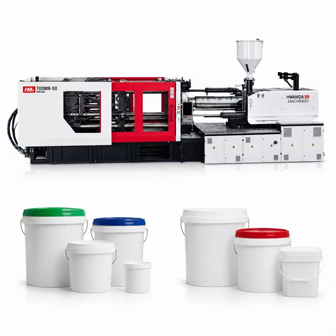
| 10 to 33 L paint buckets | M8SII paint bucket series | Configured for bucket molds, robot take-out or IML |
| Fruit crates, baskets, logistics crates | FCII crate and basket series | Sized for crate mold dimensions and shot weights |
| PVC, PPR and PP pipe fittings | PVC fitting machines | PVC-specific plasticizing package |
| Cosmetic packaging | M8-SII-P cosmetic packaging machines | Machine configuration for cosmetic packaging production |
FAQ
Frequently asked questions
How do I calculate the clamping force I need?
Multiply the total projected area of all cavities and runners in cm2 by the typical cavity pressure in kgf/cm2, then divide by 1,000 to get tons force. Add a 10 to 20 percent margin and convert to kN by multiplying tons by about 9.81.
What percentage of the shot capacity should I use?
Aim for 20 to 80 percent of the screw's shot capacity, ideally 30 to 65 percent for heat-sensitive materials. Too small a shot increases residence time; too large leaves no cushion.
Why are shot weights quoted in PS?
PS is the industry reference material. Convert to your material by the ratio of melt densities; PP and PE give roughly 85 to 90 percent of the PS value.
Can I choose a bigger screw instead of a bigger machine?
Often yes. Machines such as the M8SII series offer several injection unit options per clamp, so a larger shot can be matched without increasing tonnage, as long as injection pressure remains sufficient.
What changes for thin-wall packaging?
Thin walls need much higher cavity pressure, very fast injection and quick dry cycles. A dedicated high-speed machine such as the SP6 series is usually the right choice.
How much margin should I add to the clamping force?
A margin of 10 to 20 percent over the calculated value is typical. Larger margins add cost and energy use without improving part quality.
What if my mold is wider than the tie-bar spacing?
You need a machine with wider tie-bar spacing, which may mean a larger model or a two-platen machine for very large molds. Confirm mold dimensions before choosing the model.
Can HWAMDA help select the machine?
Yes. Send the part, mold and output data and HWAMDA will recommend a machine, mold and automation configuration as one matched cell.