 HWAMDA

Resources
Injection Molding Machine Tonnage Calculator
Calculate the clamping force your mold needs from projected area, cavity pressure, cavities and safety factor, then match it to a machine size.
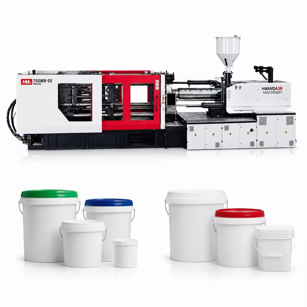
How to use the tonnage calculator
Clamping force must be high enough to keep the mold closed against the pressure of the melt in the cavities. Too little force causes flash and dimensional problems; too much wastes energy, increases mold wear and means paying for a larger machine than needed.
Enter four values: the projected area of one part in cm², the estimated cavity pressure in kgf/cm², the number of cavities, and a safety factor. The calculator returns the required clamping force in metric tonnes. Use it for an early estimate, then confirm with mold flow analysis or your mold designer for critical projects.
The formula
Clamping force (t) = projected area per part (cm²) × number of cavities × cavity pressure (kgf/cm²) ÷ 1,000 × safety factor.
Dividing by 1,000 converts kilograms-force to metric tonnes. A safety factor of 1.1 to 1.2 is typical; use the upper end when wall thickness is uncertain, the material is easy-flowing and prone to flash, or the mold has a large runner area.
How to measure projected area
Projected area is the area of the part's shadow seen in the direction of mold opening, not its total surface area. Holes that pass all the way through can be subtracted. For a round cup or container, use the outer rim diameter: area = 3.14 × (D/2)². For a rectangular part, use length × width of the outline at the parting line.
Include the runner and sprue area for cold runner molds, since melt pressure acts there too. Add the projected area of the runners once for the whole mold, or as a typical allowance spread it across cavities, often 10 to 20 percent of part area for cold runners. Hot runner molds normally need no runner allowance because the manifold sits inside the mold plates.
Typical cavity pressure by material and wall thickness
Cavity pressure depends on the material's viscosity and the ratio of flow length to wall thickness. Thin walls and long flow paths need much higher pressure. The table gives typical working values for estimating.
| Material / application | Flow ratio (L/t) | Typical cavity pressure (kgf/cm²) |
|---|---|---|
| PP, PE thick-wall parts (2.5 mm and up) | Below 100:1 | 250 to 350 |
| PP, PE general parts (1.5 to 2.5 mm) | 100 to 200:1 | 300 to 450 |
| PP thin-wall packaging (0.4 to 0.8 mm) | 200 to 350:1 | 450 to 600 or more |
| PS, ABS, SAN general parts | 100 to 200:1 | 350 to 500 |
| PA, POM technical parts | 100 to 200:1 | 400 to 600 |
| PC, PMMA, PC/ABS | 100 to 150:1 | 500 to 700 |
| PVC rigid fittings | Below 150:1 | 400 to 600 |
| PET preforms | Low, thick wall | 350 to 500 |
Worked example
A PP thin-wall food container has an outer rim of 120 × 90 mm, so its projected area is 12 × 9 = 108 cm². The mold has 4 cavities on a hot runner, wall thickness is 0.6 mm and the flow ratio is about 250:1, so a cavity pressure of 550 kgf/cm² is a reasonable estimate. With a safety factor of 1.15:
108 × 4 × 550 ÷ 1,000 × 1.15 = 273 t. That is about 2,680 kN, so a machine in the 300 t class (around 3,000 kN) is a sensible starting point, provided the mold fits between the tie bars and the shot size and injection speed suit thin-wall molding.
Converting tonnes and kN
Machine specifications are often given in kN. One metric tonne of force is about 9.81 kN, so multiply tonnes by 9.81 to get kN, or divide kN by 9.81 to get tonnes. For quick estimates, 1 t ≈ 10 kN is close enough: a 3,080 kN machine is roughly 314 t. One US ton equals about 0.907 metric tonnes.
Next steps: tie bars, platens and shot size
Clamping force is only the first filter. Check that the mold width and height fit between the tie bars, that the platen size supports the mold footprint, that the mold height lies between the minimum and maximum mold thickness, and that the opening stroke allows part removal. Then confirm shot size with the shot size calculator and check injection speed and pressure for your wall thickness.
- 900 to 33,000 kN
- M8SII servo-hydraulic general-purpose series, 25 models with several injection-unit options each.
- 3,080 to 5,500 kN
- SP6 high-speed thin-wall series for cups, food containers and IML packaging.
- 2,180 to 8,000 kN
- DP multi-material series for two- or three-color and multi-material parts.
- 6,500 to 24,000 kN and above
- DU II two-platen series, plus DU3300II, for large molds.
Send your part drawing and mold data to HWAMDA for a machine–mold matching review.
FAQ
Frequently asked questions
How do I calculate clamping force for injection molding?
Multiply the projected area per part in cm² by the number of cavities and the cavity pressure in kgf/cm², divide by 1,000 to get tonnes, and apply a safety factor of about 1.1 to 1.2.
What cavity pressure should I use?
Typical values range from about 250 to 350 kgf/cm² for thick-wall PP and PE up to 450 to 600 kgf/cm² or more for thin-wall packaging. Engineering resins such as PC typically need 500 to 700 kgf/cm².
Should the runner be included in projected area?
Yes for cold runner molds, because melt pressure acts on the runner as well. Hot runner molds normally need no runner allowance.
How many kN is one tonne of clamping force?
One metric tonne is about 9.81 kN. Multiply tonnes by 9.81 to get kN.
Is a bigger machine always safer?
No. An oversized machine costs more, uses more energy and can make shot control less precise. Choose the smallest machine that meets clamp force, mold size and shot requirements with a sensible margin.
What else do I check after tonnage?
Tie-bar spacing, platen size, mold thickness range, opening stroke, shot size and injection speed and pressure.
Discuss your production requirement
Send the information you already have. We can help structure missing technical inputs.